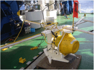
Australian OBEM Australian OBM (Type 1) Australian OBM (Type 2)
ERI-OBEM (Type 1) ERI-OBEM (Type 2) IFREE/JAMSTEC-OBEM
Kobe OBEM US OBEM US OBE
KR05-17かいれい調査航海概要
研究課題名:
海底電位差磁力計による沈み込み・前弧・島弧・背弧系(中部マリアナ海域)の横断探査その1
(海底電位差磁力計、海底電位差計、海底磁力計の設置)
| 氏名 | 所属機関名 | 役職名 |
| 島伸和 | 神戸大学 | 助教授 |
| 馬場聖至 | 東京大学 | 助手 |
| 岩本久則 | 神戸大学 | 大学院生 |
| 松野哲男 | 神戸大学 | 〃 |
| 馬場祐太 | 東京大学 | 〃 |
| Alan Chave | ウッズホール海洋研究所 (米) | Senior Scientist |
| John Bailey | 〃 | Engineer |
| Anthony White | Flinders University (豪) | Associate Professor |
| Goran Boren | 〃 | 大学院生 |
| 鈴木 啓吾 | 日海事 | 部員 |
| 小村 舞 | 〃 | 〃 |
調査海域:
中部マリアナ海域
(16°00.0′N、 20°00.0′N、141°00.0′E、151°00.0′Eの各経緯度線で囲まれる範囲)
実施期間:
2005年12月10日(土)〜2005年12月26日(月)
調査航海概要:
1. Purposes
This project is a Japan, US, and Australia collaborative research effort.
We will carry out a marine magnetotelluric transect across the central
Mariana subduction system using ocean bottom electro-magnetometers (OBEMs),
ocean bottom electrometers (OBEs), and ocean bottom magnetometers (OBMs)
to provide a comprehensive image of the electrical conductivity structure
of the Mariana island-arc system extending from the Pacific ocean to the
West Mariana Ridge (remnant arc) through the Marina Trough. Subduction
zones are fundamental to Earth recycling, controlling the return of crustal
materials into the mantle and the partitioning of some fraction back to
the surface. The Mariana subduction system is the classic example
of an intra-oceanic arc, trench, and back-arc system. Our transect across
the central Mariana subduction system, which includes three upwellings
of serpentine diapirs, arc volcanism, and back-arc spreading, will address
issues of hydration of the mantle wedge resulting from subduction and the
nature and distribution of subsequent melting through estimation of the
electrical conductivity structure. This will make a breakthrough
for understanding mantle dynamics related to plate subduction.
2.
Preliminary Results
2-1. OBEM, OBM, and OBE deployment and positioning
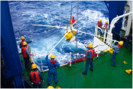
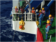
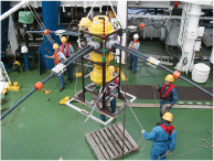
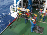
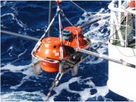
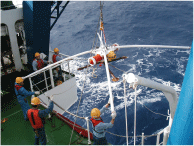
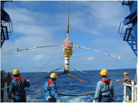
Deployments of OBEM, OBM, and OBE (Photo 1) were made at 40 sites across the Mariana Trench and back arc spreading centre. Site positions are given in Figure 1. East of the Trench sites spacing was approximately 40 km, but to the west the spacing was closer, particularly in the vicinity of the back arc spreading centre, where the sites were only a few km apart. The deployments were made starting from the east end of the transect, but the exact order of deployment was varied to fit in with SeaBeam surveys and positioning surveys during night time hours. Several instruments were tracked acoustically to the bottom (sites 36, 39, and 6) but, in general, the instruments were tracked only for a short time after deployment.
All deployments were made using the A-frame, except for 4 Australian OBM’s which were small enough to be released from a small davit. All deployments were successful except for a single case where an anchor ballast weight was dislodged from an OBEM (site 6). This instrument had to be recovered from the sea surface. It was re-deployed successfully after a new anchor weight was fabricated and fitted to the instrument.
Positioning of the instruments on the ocean floor at 29 sites was performed
during night time hours. At most sites a single OBEM was deployed,
but at 7 sites an OBM from the Australian group was deployed with an from
the US group to make a combined site. In these cases both instruments
were positioned independently. “Kairei” SSBL (Super Short Base
Line) positioning system was used for all the Kobe OBEM’s and some of
the JAMSTEC OBEM’s. A ping every 16 seconds was transmitted from
the acoustic on board unit, and the response from the transponder of the
OBEM was received by “Kairei” SSBL (Super Short Base Line). The final
position of all instruments at 29 sites were determined by using slant
ranges between ship and transponder.
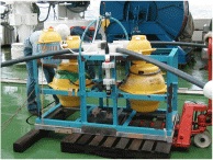
Photo 1
Australian OBEM Australian OBM (Type 1) Australian
OBM (Type 2)
ERI-OBEM (Type 1)
ERI-OBEM (Type 2) IFREE/JAMSTEC-OBEM
Kobe OBEM
US OBEM
US OBE
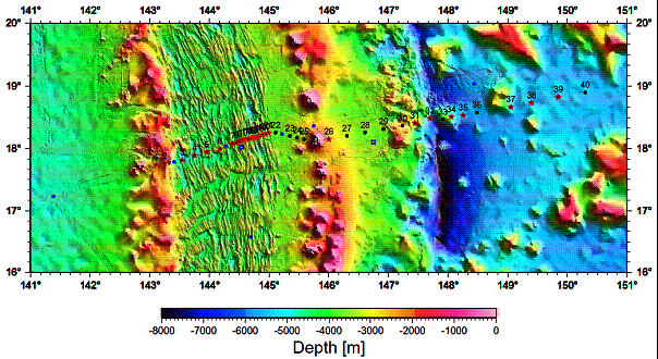
Figure 1a.
Location map of OBEM,OBM and OBE. Black circles, red stars, blue symbols
show launched positions, show settled positions, and OBEM positions from
previous studies, respectively.
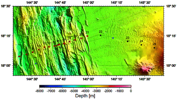
Figure 1b.
Location map of OBEM,OBM and OBE near the spreading axis of Mariana Trough.
The symbols are the same as Figure 1a.
2-2.
Surface Geophysical Survey
We conducted a surface geophysical survey mainly during night time hours
to collect multi-narrow beam bathymetry, gravity field, and magnetic field
data. Some of the area had detailed SeaBeam bathymetry available,
but other areas along the transect had to be surveyed before exact instrument
deployment sites could be decided. A map of the transect area is
shown in Figure 2. Multi-narrow beam bathymetric feature was obtained
by SeaBeam 2112, which also provides a backscatter image, which will be
processed after the cruise. An XBT was done on 13th December. The
DGPS (differential global positioning system) was used to derive the best
ship location.
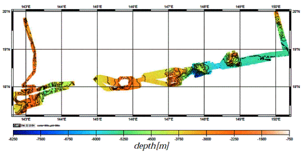
Figure 2. Topography map in the survey area
3.
Summary and Future Studies
We successfully deployed 33 OBEMs, 7 OBMs, and 7 OBEs at 40 sites.
Positioning of the instruments on the ocean floor at 29 sites was performed,
which allows us to determine the positions precisely. All the instruments
measure geomagnetic and/or electric fields continuously until we will recover
them in September, 2006. After the recovery, these data will provide
a comprehensive image of the electrical conductivity structure for the
Mariana island-arc system extending from the Pacific ocean to the West
Mariana Ridge (remnant arc) through the Marina Trough. Further, the
surface geophysical survey data will be used for the topographic correction
of electro-magnetic data and provide additional information for an interpretation
of electrical conductivity structure. These results will make a breakthrough
for understanding mantle dynamics related to plate subduction.
Acknowledgement
We gratefully recognize the efforts of the officers and crew (Shinya Ryono, captain) of the R/V Kairei during the cruise. We thank all the support staffs in JAMSTEC. We also thank H. Fujimoto for providing us a ring laser gyrocompass, which was used for our STCM measurement. This research was supported by Grant-In-Aid for Scientific Research (B)(1)(No. 15340149), Japan Society for the Promotion of Science, “The 21st Century COE Program of Origin and Evolution of Planetary Systems” and “Stagnant Slab Project (No. 17037003)” in Ministry of Education, Culture, Sports, Science, and Technology, Flinders University, and U.S. National Science Foundation.